Atari Punk Console Breadboard Soldering and Design
The APC is the first synthetizer circuit Jonah introduced me this year, beyond the circuit and its history themselves, the name of this circuit inspired me to make it a minimialist steampunk tool, that I describe in this documentation.
Interface Design for the APC
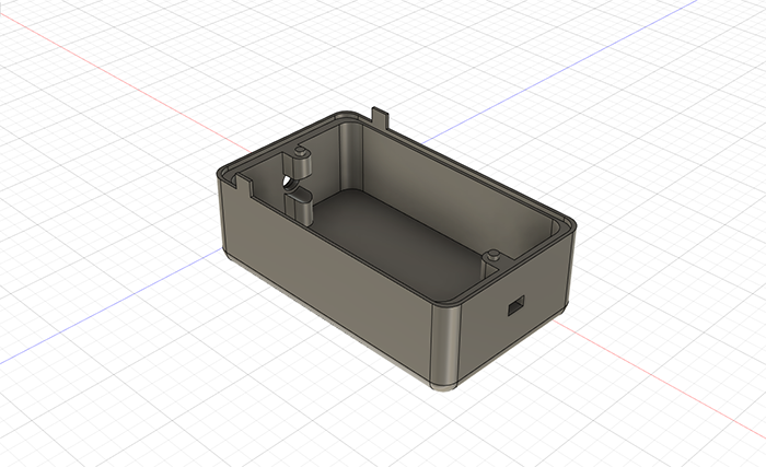
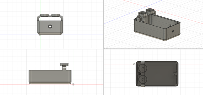
I imagined a simple interface for the APC, with the potentiometers accessible, and a box in which we can hold the battery, with on the outside a switch and a 3.5mm Jack on opposite sides.
The APC Circuit
For more information about the Atari Punk Console you can follow this link to the making of the APC on a PCB using Eagle and how the circuit behaves :
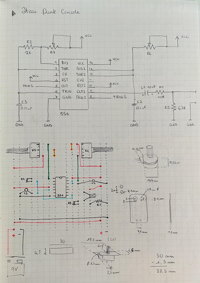
Schematics circuit and physical circuit I drawn, with some mesurements of some components I'm using.
Here are all the components and parts I'm using :
| Quantity | Component | Value |
|---|---|---|
| 1 | 556 dual chip | - |
| 2 | Potentiometers | 10K |
| 1 | Resistor | 1K |
| 1 | Resistor | 4,7K |
| 1 | Resistor | 10K |
| 1 | Capacitor | 0.01uf |
| 1 | Capacitor | 0.1uf |
| 1 | Polarized Capacitor | |
| 1 | 3.5mm Jack | - |
| 1 | DC Barrel | 9V |
| 1 | Battery | 9V |
| 1 | Switch | - |
| 1 | Breadboard | Electrocookie 1/2 sized |
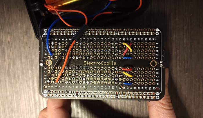
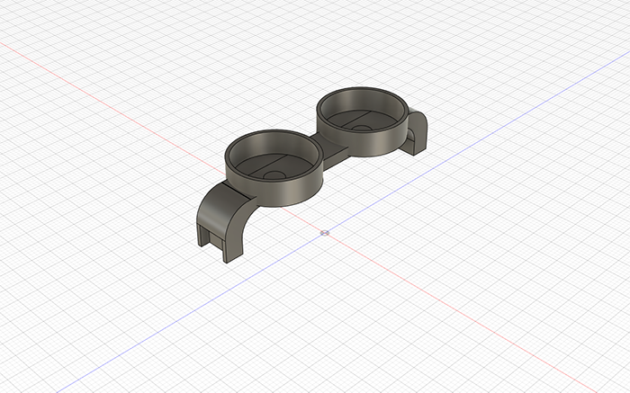
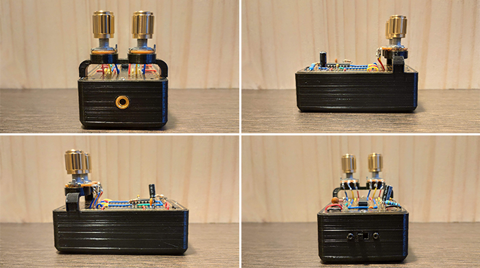
I'm using the "verso" side of the breadboard, to only have the golden traces visible. A thing that I would modify it this design is the system holding the potentiometers that is clipped to the box. A better solution would have been to attach this system to the board. The solution in use is fragile, the risk to break the wires soldered to the potentiometers by accessing the battery part is high.
Assembly & Test
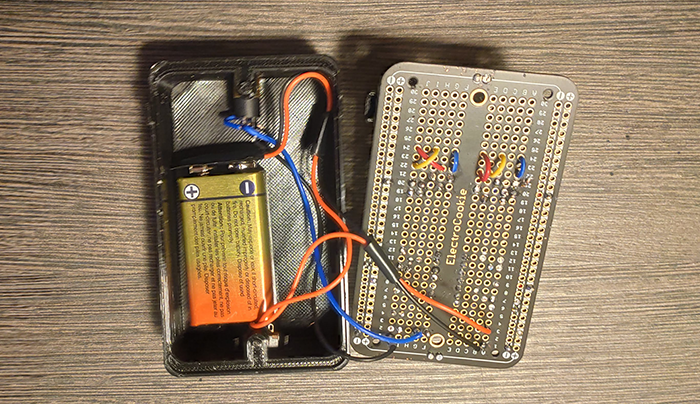
When all the components were soldered on the breadboard and in the box :
The Atari spleen : (Sorry for the quality, the 3D printer was running when I recorded this.)